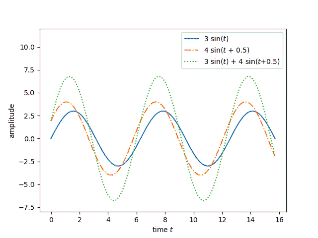
Suppose you have two sinusoidal functions with the same frequency ω but with different phases and different amplitudes:
f(t) = A sin(ωt)
and
g(t) = B sin(ωt + φ).
Then their sum is another sine wave with the same frequency
h(t) = C sin(ωt + ψ).
Note that this includes cosines as a special case since a cosine is a sine with phase shift φ = 90°.

This post will
- prove that the sum of sine waves is another sine wave,
- show how to find its amplitude and phase, and
- discuss the significance of this result in signal processing.
Finding the amplitude and phase
Note f + g and h both satisfy the second order differential equation
y” = − ω² y
Therefore if they also satisfy the same initial conditions y(0) and y‘(0) then they’re the same function.
The functions f + g and h are equal at 0 if
B sin(φ) = C sin(ψ).
and their derivatives are equal at 0 if
ω A + ω B cos(φ) = ω C cos(ψ).
Taking ratios says that
tan(ψ) = B sin(φ) / (A + B cos(φ))
or
ψ = arctan( B sin(φ) / (A + B cos(φ)) ).
Once we have ψ, we solve for C and find
C = B sin(φ) / sin(ψ).
Special case of sine and cosine
Let’s look at the special case of φ = 90°, i.e. adding A sin(ωt) and B cos(ωt). Then sin(φ) = 1 and cos(φ) = 0, and the equation for ψ simplifies to
ψ = arctan(B/A).
If an angle has tangent B/A, then it’s sine is B / √(A² + B²), and so we have
C = √(A² + B²).
Linear time invariant (LTI) systems
A linear, time-invariant system can differentiate or integrate signals. It can change their amplitude or phase. And it can add two signals together.
It’s easy to see that changing the amplitude or phase of a signal doesn’t change its frequency. It’s also easy to see that differentiation and integration of sine waves doesn’t change their frequency. But it’s not as clear that adding two sines with the same frequency doesn’t change their frequency. Here we’ve shown that’s the case.
Bode plots are a way to show how an LTI system changes in response to changes in its inputs. These plots show what happens to the amplitude and to the phase. They don’t need to show what happens to the frequency because the frequency doesn’t change.

I think it makes more sense to think of everything in terms of complex exponentials (with the real part corresponding to position). Then all phase shifts just become complex coefficients and addition is easy to visualize geometrically.
I think it’s easier to see what’s going on, and to do the algebraic manipulations, if this is done in the Fourier domain.
Excellent reference Mr. Cook! I tried several examples and your math works to confirm to me it is a great teaching tool. You showed in a compact way why phasors/vectors work and how this can be easily related to phase shifts between voltage and current time domain sine waves when you have resistive and reactance loads. Instead of the Euler exponential Laplace kind of transformation time domain to frequency domain which can boggle people, you simply showed why time domain math (yuckie) can be easily transformed to vector math (goodie) works at a given frequency. This is the best presentation I have ever seen on this. Thanks!